Documentation
CFD
Tutorials
UI
Model Cleaning

In this article we will go through how to clean up a Rhino model as a preparation for running a CFD simulation.
Table of Contents
Lighthouse Model
We are so lucky that the Danish architecture studio 3XN have provided us with a real-life project. The model is from the Lighthouse project in the harbour of Aarhus, Denmark. We got the building volumes, that they have made, which is the perfect stage to run the CFD model on as it does not have too many details.
Closed Volumes
At Compute we use OpenFOAM behind the scenes to run the simulation. OpenFOAM (and most other CFD software) requires that the geometry, you want to use is closed meshes. Rhino is actually not a mesh tool, but it can export its geometry as meshes, which we will take advantage of.
A Rhino model will typically be made of surfaces, extrusions and polysurfaces. As part of the model clean up it is our task to make sure that all that geometry is closed. The process is to make a visual inspection of the geometry in the model. This model is actually really good and there is only a few places, where we need to redraw.

In this model there are not that many objects, so it is not a problem to go through them all to see if they are closed.
In cases with a lot of objects, you might want to use some of Rhino's Sel commands to select different types of geometry or even use Grasshopper.
Going through this model, we notice that there are four buildings to the left, that are open surfaces.
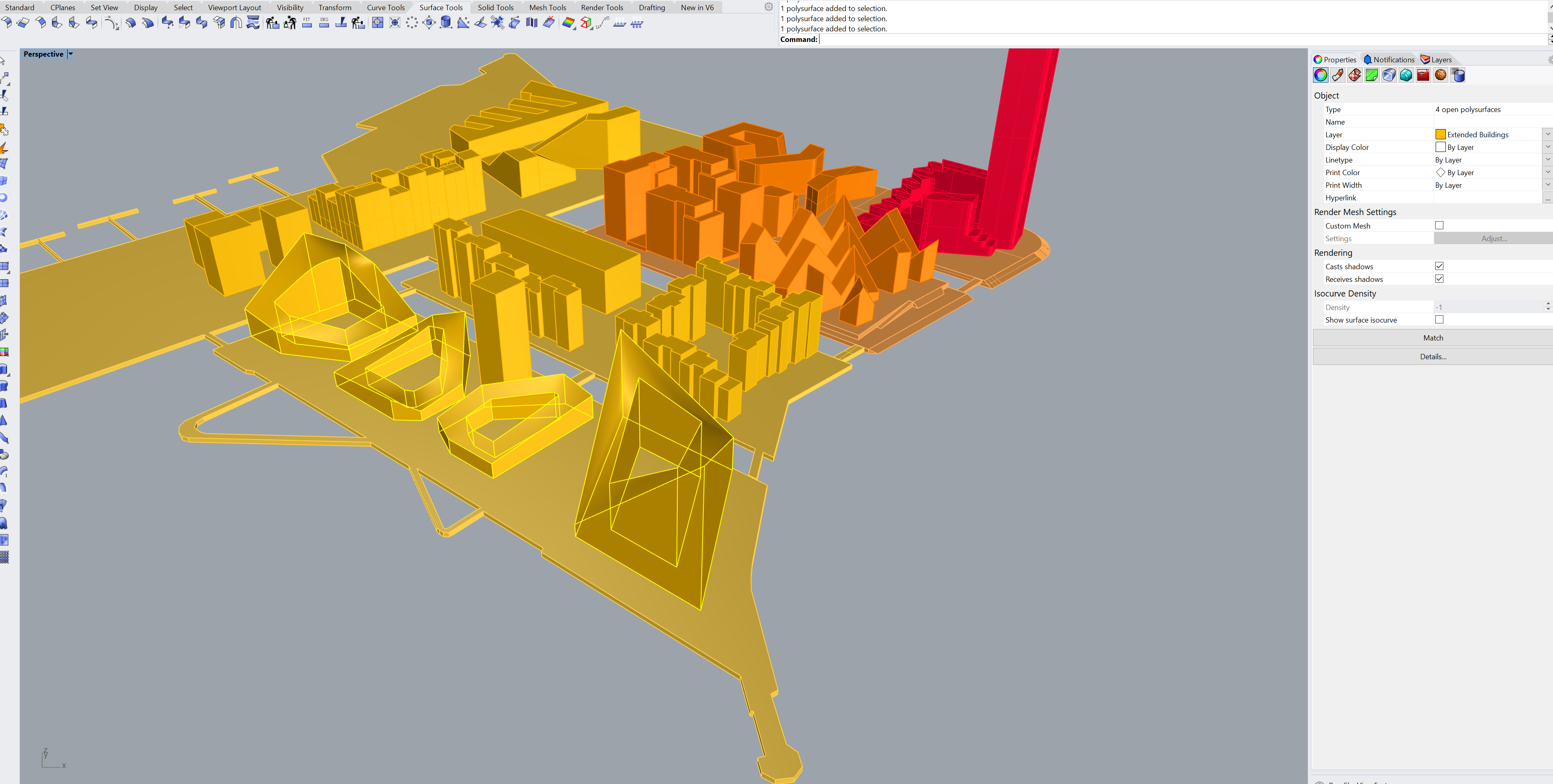
That is going to be a problem for us later on, if we don't fix it now. The procedure to fix it is simple enough. You just draw an approximation of the geometry again and make sure that this time it is closed.

Another thing to be aware of is if there is any obscure geometry or if there is something that should align, but is not really aligning. It might not cause the simulation to fail, but it will affect the meshing and either increase the number of cells or cause some cells to be skewed, which effects the accuracy of the model.
In this model there is a bridge next to the Lighthouse itself that doesn't really align to the top of the pavement.

Had the bridge been further away from the area of interest (i.e. near proximity of the Lighthouse), you could probably just delete it. But since it is so close, we will just remodel it and make sure it snaps to the top of the pavement.

With all the modifications the model now looks like as shown below. At a quick glance it doesn't look that different, which is part of the point. You shouldn't change it so much that it doesn't look like itself anymore. Then it is not the same model!

Model Units
The next step is to check, whether or not the model has the right size or is drawn in the right units.
In Rhino, you can see the model units by writing Units in the Rhino console.

This model we got from 3XN was drawn in millimeters, so we have to change that to meters and scale it accordingly.
Sometimes a model can have the right units, but the person who drew it, drew it in another scale.
So it is always good to take a quick measure of a building height (you can use distance), to see whether the model fits the units.

Origin
Since this is a preparation for running a virtual wind tunnel, where we rotate that geometry several times,
it is really important that the geometry is centered around the model origin.
In this case it is. 0,0,0 is right under the Lighthouse, which is perfect.
Layers
The next step is to separate the geometry into different layers, so it is easier later on to give the geometry the appropriate mesh levels.

For the purpose of this case, we are going to create 6 new layers:
- Site
- Buildings
- Ground
- Analysis Surface
- Context - Near
- Buildings
- Ground
- Context - Far
- Buildings
- Ground
The idea behind putting the geometry in different layers is that we want to have a higher
resolution closer to the area of interest (i.e. the Lighthouse), and the geometry further away can be of a lower
resolution, so we don't get a massive number of cells.
So that is why we divide the geometry into 3 groups: Site, Context - Near and Context - Far

The Lighthouse itself goes to Site::Buildings, but we don't want to put all the island it stands on into Site::Ground.
Therefore, we will make a cut in the geometry in the middle of the island to separate the area around the Lighthouse
and the ground where the two buildings stand.

Analysis Surfaces
Now that we have cleaned geometry, and it is separated into layers based on the distance to the Lighthouse,
we are only missing one last thing. It is to create the Analysis Surfaces.
This is the surfaces we want to get the results from later on, when we create the probes.

For the Lighthouse we are interested in getting values around the building, so we are going to create a surface that sits around it and then two in the yard.
Final Model
